|
|
||||
|
|
|
|
|
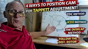
4 Positioning Methods used for Tappet Adjustment |
|
All the following methods describe how and where the camshaft is positioned to enable the tappets to be set, no matter if you have a hydraulic cam or a solid lifter cam. If you are going to set the tappets static then you will use one of these methods to position the camshaft so that the tappets you want to adjust are positioned on the base circle (heel) of the cam lobe. All tappets are initially adjusted with the engine stationary, solid or hydraulic. There are four positioning methods used depending on the engine type, access to crankshaft and difficulty of rotating the engine. The four common methods are and listed below.
If you have an overhead camshaft (OHC) engine then positioning the cam is much easier because you can actually see it and where the rockers are touching on the cam. Using a cam profile I made recently, the following video explains the different methods and actually shows you the camshaft position using the different methods. Use it in conjunction with this article to determine the best method for you.
1) Distributor Rotor Method: A great method for total beginners as you simply can't go wrong. If the distributor is still in the engine and you know the engine was running then this method is OK to use. Simply remove the distributor cap & follow the rotor button. Align the tip of the rotor up to a HT lead in the cap. That cylinder will be on TDC ready to fire and therefore both valves will be closed and the lifter will be on the base circle of the camshaft. You will be able to adjust both valves. 2) Valve Rocking/Overlap Method:
3) Inlet just Closed Exhaust just Opening. (ICEO) or (EOIC)
I have only ever used this three times, once before I was an apprentice, once during my apprenticeship and once doing the tappets on my 3cyl Alto. You work on one tappet at a time. Pick a cylinder and observe the valve movement as you turn the engine slowly. When the inlet valve just shuts, stop and set the exhaust valve clearance on the same cylinder. Continue to rotate the engine until the exhaust valve on this cylinder just starts to open, stop and set the Inlet valve clearance. That's it, go on to the next cylinder and repeat the same process. The photos show just where the tappet is on the camshaft when in both positions. This guarantees that the tappet is near in the centre of the base circle where some mechanics believe it should be set, therefore a lot of people believe this is the only way to do it. This method does have its place and I would use it on 1, 2, 3 and 5 cylinder engines, when no two pistons are at TDC at the same time. This method is very crank intensive and takes a long time to get through the procedure especially a V8 or more cylinders.
Myth vs Fact: Tappet Adjustment – For those who like to over complicate things Myth: “You must adjust your tappets only when the lifter is opposite the cam lobe (ie. the ICEO method), during a full moon, with the engine facing magnetic north. Otherwise, total engine failure is guaranteed.” Ha Ha, funny aren't I. Fact: Nope. The tappet can be adjusted anywhere on the base circle for 180 deg around the base circle and even further if using a small camshaft profile. That’s the smooth, circular bit of the camshaft that doesn’t do anything exciting. Why? Because it’s concentric with the camshaft’s axis. Same radius all the way around, so the valve clearance will be the same anywhere along that base circle - not just when the lobe is directly opposite. Ground-breaking, right? The eccentric part is the cam lobe itself (the raised portion that causes valve lift), which deviates from the base circle and creates the variable lift as the camshaft rotates. Bottom line: If your camshaft is properly ground (as it should be), your tappet doesn’t care whether it’s 90° before or after the lobe. It will be sitting on the base circle which is ground concentric to the camshaft axis of rotation. 4) TDC Method:
This method was reserved for diesels many years ago as they are extremely difficult to turn over due to higher compressions. Nowadays (pre 2000) many car manufacturers that still use solid tappet camshafts also adopted this method for petrol engines. This method only requires you to turn the engine twice. The No.1 cylinder is set on either the overlap of valves on TDC or compression TDC, then half of the valves in the engine are set. The engine is then rotated by 360 deg and returned to TDC and then the remaining valves are set. Fairly simple, all you need to do is observe #1 cyl or its opposite while your turning the engine to the TDC mark initially. The opposite cylinder is marked in the tables below eg. on a 6 cyl both #1 & #6 are at TDC at the same time. All you have to know is which one is on compression so you can use the tables below to start setting. If the distributor is in and the car was running, point the rotor to #1. You are on compression #1 and just follow the table to adjust the correct valves. Another way to do it, is observe the rocker arms or lifters. You are looking for the exhaust to be closing & the inlet to start opening on either #1 prefereably or its opposite. Once that happens line up the timing mark to TDC, you won't be far from it when you notice the inlet valve start to open. The opposite cylinder will be on TDC compression. Whichever cylinder you start with, ie. if you started with TDC compression #1 which is the blue table below, you will set the tappets according to the instructions within the blue table. Then you will rotate the engine 360 degree & set the tappets according to the orange instructions. If however you started with the orange table then carry out the adjustment on the tappets in the orange section, then rotate the engine 360 degrees and set the tappet to the blue instructions. Regardless of whether the camshaft is driven by a chain or connected to the crank by gears, it does not change which valves need setting from the tables below. Go ahead, find your firing order in the table below, print out the appropriate file and get into it. Just follow what I do in the Chev video and transpose it to your engine. Just in case you don't know, the TDC mark on the harmonic balancer needs to be reasonably accurate, at least within 10 degrees either way. I have made these tables available to print in Word format. Just choose which one suits your engine 4 cyl 6 cyl 8 cyl 4 Cylinder firing orders: In-line engines & Flat plane Firing order 1-3-4-2
Firing order 1-2-4-3
6 cylinder firing orders: In-line engines, V6 & flat plane
Firing order 1-5-3-6-2-4
Firing order 1-4-2-6-3-5
Firing order 1-6-5-4-3-2
Firing order 1-2-3-4-5-6
8 cylinders firing orders: In-line engines & 90 deg V 90 degree banked V8 engines can also be adjusted using the TDC method. A very convenient way to do 8 cylinders without constantly turning the engine over 8 times to do all the tappets if your using the overlap method and much less labour intensive than the ICEO method that so many seem to love. I have listed 7 firing orders that I am aware off, if you have another one let me know & I will add it to the list below. Firing order 1-3-7-2-6-5-4-8
Firing order 1-8-4-3-6-5-7-2
Firing order 1-8-7-3-6-5-4-2 The 4/7 swap for the Chev
Firing order 1-2-7-8-4-5-6-3
Firing order 1-5-4-2-6-3-7-8
Firing order 1-5-4-8-6-3-7-2
Firing order 1-8-7-2-6-5-4-3
|