Hydraulic lifters, cam followers, tappet and what ever other name you know them by are all the same thing. They automatically maintain the valve lash at zero clearance at all operating temperatures and once adjusted correctly will stay in adjustment for the life of the engine.
|
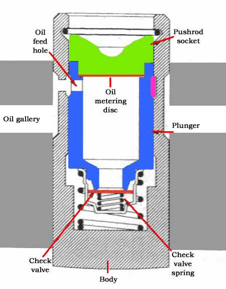
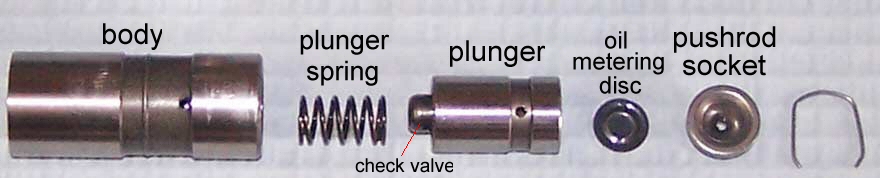
When the lifter is resting on the base circle of the cam the big plunger spring initially takes up all the clearance in the valve train. Oil under pressure from the oil gallery enters the body through the feed hole and into the plunger space. The oil passes through the hole at the base of the plunger past the check disc or check ball depending on design and fills the space below the plunger. This provides additional pressure against the plunger to take up any clearance. As the camshaft rotates the body is raised on the cam lobe against the push rod and therefore against the valve spring. This applies pressure to the oil in the chamber below the plunger and causes the check valve to close. This now causes the lifter to act as a solid unit and move the push rod up to open the valve. A small amount of oil is allowed to pass between the plunger and the body and this is known as leak down. Once the lifter is returned to the base circle, the clearance is taken up by the plunger spring and oil pressure under the plunger once again when fresh oil is pumped in to replace the small amount lost during leak down. While all this is going on constant supply of metered oil is fed up through the push rod to lubricate the valve train via the oil metering disc that is placed between the plunger and the push rod socket. The lifter has a working range of about .160" (4mm) This is the distance an empty plunger travels down the body until it stops. There is an external groove in the plunger which matches an internal groove in the body. I have highlighted this groove in purple on the right side of the lifter. If the plunger is pushed down 4mm you will lose compression because the lifter will now be a solid tappet and will hold the valves slightly off their seats. The result is an engine that won't run. |
|
|
|
This is the formula I used for a Holden 6cyl engine with a fine thread stud on the fulcrum. The formula: D = F x (A + B) / B short version D = F x 1.68 This formula works out approximately how far the push rod will push the plunger into the body when the fulcrum nut is turned a specified distance (F). If your clever at geometry, you will know this is not quite exact but for our purposes this will be close enough as the error is only a thou or so. In this example the pitch of the thread is 24TPI which gives us .041" with 1 full turn of the stud nut at point F. |
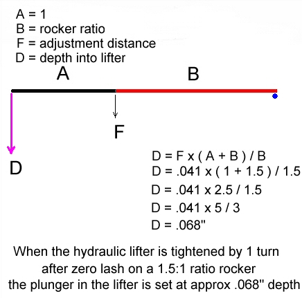
There is a lot of confusion out there about how far to adjust the stud nut after zero lash. I have heard some beauties in my time so I would like to share my opinion. You may have read my other articles on Hydraulic lifter adjustment in the TechTalk section and know I advocate 1/2 to 3/4 turns on the adjuster after zero lash. That equates to .050" plunger depth into the lifter, more than satisfactory. This clearance will last the life cycle of the rocker train components without any further adjustment.

You will hear mechanics that set the adjustment to only 1/8 to 1/4 turn. There is only one logical reason to set them so loose in a standard lifter and that is to lessen the sometimes catastrophic effect of lifter pump up which I will talk about shortly. At this setting you will need to check and re-adjust the lifters several times over the valve train life cycle. The reason being is that once this amount of wear takes place in the valve train the lifters will start to be noisy because they can't take up the clearance any more since the plunger will be at the top of its travel against the circlip. There is also the danger of dislodging the circlip if this is left unchecked,(the main danger of going loose). In an anti-pump up lifter however, the faster leak down of the lifter will cause the plunger to sink further into the body before hydraulic lock takes place and the lifter operates as a solid unit. So to ensure the plunger does not bottom out a 1/4 turn is used by many mechanics for safety, but at this adjustment there will still need to be more frequent adjustments done.
On the other scale if the lifters are adjusted to 2 turns, you will only have .025" left in the plunger depth before it may lock up. So you need to steer away from going down to tight on the initial adjustment. This condition is the main reason I advocate 3/4 turn because it will never get to the stage where the plunger will go that deep taking into account the wear of the valve train components.
On the other hand, you may be deliberately tightening the nut down that far to make geometry adjustments. Have a think of what is happening to the effective push rod length during the adjustment. A tight adjustment is like shortening the push rod. You can in effect shorten the push rod by nearly .100" by screwing in the adjuster nut close to maximum distance of about 1 3/4 turns. The lifter will still work but will need more periodic servicing adjustments to ensure the lifter does not get tighter and become solid prematurely.
So you see, you can employ a bit of trickery to the hydraulic lifter to make geometry adjustments to the rocker arms. Tread carefully though, don't set and forget like you can with only 3/4 turn on the nut. If you adjusted tight or loose at each end of the extremes, you will need to incorporate a regular tappet adjustment into your servicing schedule.
Lifter Pump-up:
This condition is often blamed on the hydraulic lifter when in fact the lifter is not responsible at all. Lifter pump up is caused when valve train components separate causing clearance. This can be caused by weak valve springs, sticking valves, sticking lifters, radical cam grind or over revving the engine. The valve continues to open even though the camshaft lobe has passed the peak lift position. This causes clearance to appear between the valve train components. The job of the lifter is to take this clearance up, so it does. When the lifter returns to the base circle the position of the plunger is now higher in the body and causes the valve to remain off its seat when it should be shut. Consequently the engine miss-fires because of no compression. There are serious consequences to this in a performance engine depending on design and the clearances of the valve to piston at TDC.
When you experience lifter pump-up, you must immediately back-off and allow the engine to idle if it is still able, or better still turn the engine off. Wait a minute or two and restart the engine. If the valves did not contact the pistons then the engine should start and run as if nothing happened. What has happened is the lifters have bled down and returned to normal state before engine start up. If you know you have not over-revved the engine then you need to inspect the valve spring tensions or the installed height to ensure the valves have not pocketed into the valve seats. This will cause the valve stem to ride extremely high which has the effect of major spring tension loss not to mention a tight lifter. Remember under tensioned valve springs will cause lifter pump-up.
Anti Pump Up Lifters:
These lifters have been around forever. It was the easy fix to control pump-up. These lifters have faster bleed-down rates that allowed the valve to close without loss of compression. But because it bleeds down so quickly it reduces valve lift. So a small loss in performance is the trade off, but this is easily made up by designing a camshaft lobe profile to compensate for this extra bleed down. The real problem here is the valve spring. Get a spring that can control the valve movement sufficiently at high RPM and the problem of pump-up is eliminated, thereby no need to go for anti-pump up lifters. You can tell an anti-pump up lifter by looking for a heavy duty circlip that retains the push rod socket in the body. This is used to prevent the lifter from falling apart should the plunger happen to pump up against the circlip.
|
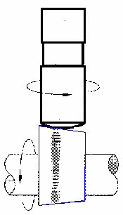
Never fit old lifters to a new camshaft. If engine repairs are required that involves removing the lifters, then do not mix them up. They must be put back on the same cam lobe. You should not fit new lifters to an old cam, there is no point especially if the old lifters showed signs of wear. Camshaft and lifters are matched once they have been used together. Lifters must turn in their bores, so if you removed extremely tight lifters, make sure they did not damage the bore on removal. Ensure they spin freely. Lifter bores should be carefully de-burred to ensure there are no sharp edges when re assembling the engine, the flex-hone does this job very well. Burrs can prevent the lifter from rotating which will result in premature wear of the lifter, cam lobes, pushrods and rocker arms. You can diagnose cam & lifter problems very easily by observing the push rod. The push rod also must spin because the rotation of the lifter imparts the spin on the push rod. If the push rods don't spin or spin at different speeds to each other, you know a problem is coming your way. Why does the lifter spin? the drawing shown shows in exaggerated form the shape of the cam surface and the base of the lifter. When the camshaft rotates it imparts a spin on the lifter. This ensures even wear between the two parts. |
|